
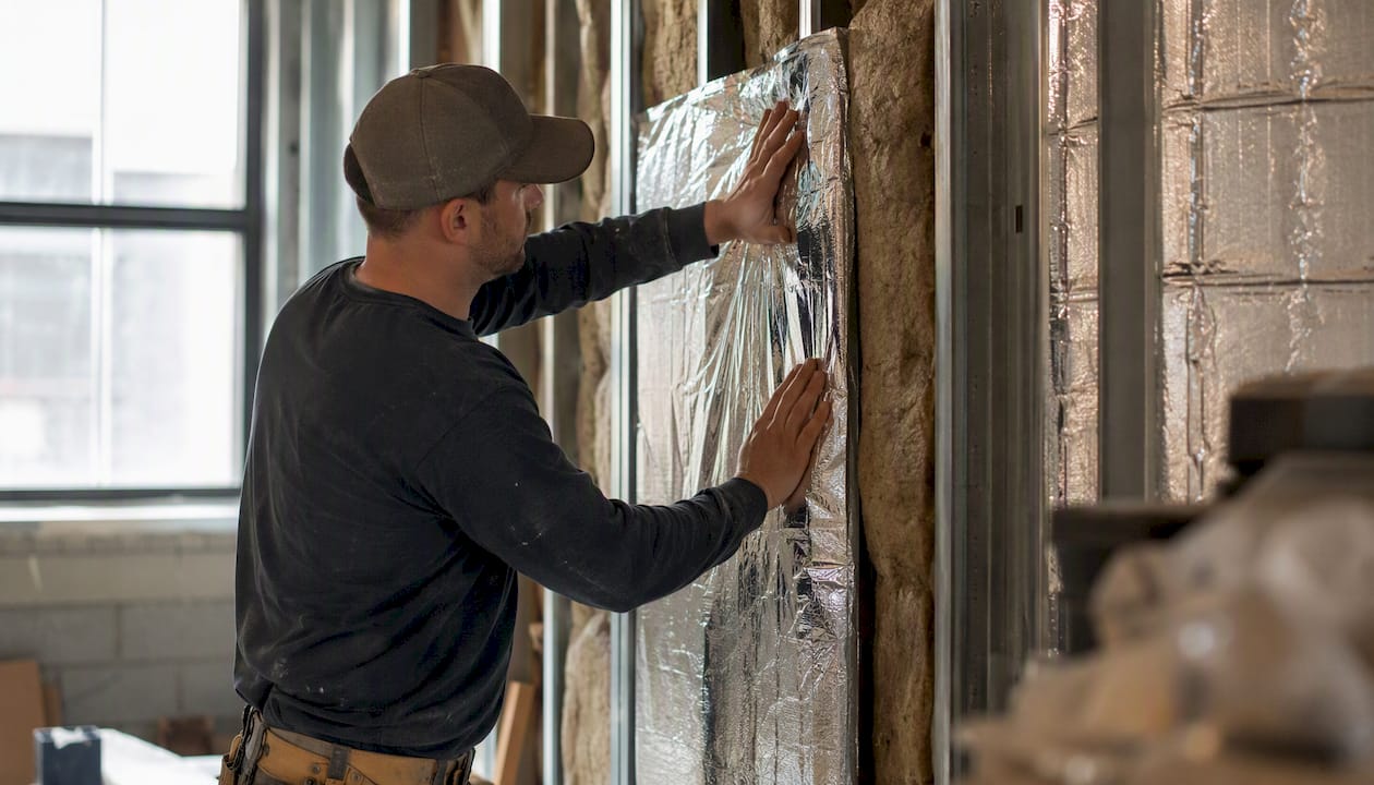
A commercial vapor barrier is a Class I vapor retarder with a permeance rating of 0.1 perms or less, installed in a building assembly specifically to control moisture diffusion and protect moisture-sensitive materials from condensation damage. According to Henry Company technical guidance, one perm equals the passage of one grain of water vapor per hour through one square foot of material at one inch of mercury pressure differential. Whether you actually need one depends on your climate zone, assembly design, and the drying paths available to the assembly — not on a blanket rule that says “always use a vapor barrier.”
The three locations where a commercial vapor barrier is most commonly specified:
- Roof assemblies over conditioned space — particularly cold-climate roofs where interior moisture drives upward into insulation
- Under-slab applications — to protect moisture-sensitive flooring finishes and interior environments from ground moisture
- Select wall assemblies — in cold climates where interior vapor pressure consistently exceeds exterior vapor pressure through the heating season
Pro Tip: Before specifying any vapor barrier, confirm your climate zone using the Energy. A product that protects a building in Minneapolis can trap destructive moisture in a building in Atlanta.
The authorities that govern specification and testing are ASTM E96 for permeance measurement, the IECC/IBC for code-driven requirements by climate zone, and Building Science Corporation for hygrothermal best practices.
Key Takeaways
A commercial vapor barrier is a Class I vapor retarder (≤0.1 perm per ASTM E96) that should be specified only when diffusion control is genuinely required and the assembly has a confirmed drying path.
| Point | Details |
|---|---|
| Class I threshold | A commercial vapor barrier must test at ≤0.1 perm per ASTM E96; Class II (0.1–1.0 perm) is a retarder, not a barrier. |
| Climate drives placement | Cold climates (zones 5–8) typically require interior vapor control; hot-humid climates (zones 1–3) often need none or exterior placement. |
| Air barrier comes first | Air leakage transports far more moisture than diffusion; a continuous air barrier is the higher-priority investment in most assemblies. |
| Specify the test method | ASTM E96 Method A and Method B produce different results; always state which method applies in the contract document. |
| Jsignorexteriors | Connecticut commercial property owners can request an envelope assessment and vapor-control consultation from Jsignorexteriors’s licensed team. |
Table of Contents
- What exactly is a commercial vapor barrier, and how is it measured?
- When should you specify a vapor barrier in a commercial building?
- How vapor drive and dew-point location actually work in commercial assemblies
- What materials are used as commercial vapor barriers?
- Where to place vapor barriers in commercial walls, roofs, and slabs
- Commercial vapor barrier installation: best practices for seams, terminations, and penetrations
- Common mistakes and failure modes in commercial vapor barrier projects
- Codes, standards, and how to write a vapor barrier specification
- Field inspection, testing, and QA for commercial vapor barriers
- A practical checklist for specifiers and property managers
- Practical notes from an experienced exterior contractor
- The case for getting vapor control right the first time
- Jsignorexteriors supports commercial vapor-control projects in Connecticut
- Sources
What exactly is a commercial vapor barrier, and how is it measured?
Permeance is the rate at which water vapor passes through a material under a pressure differential. The unit is the perm, and the lower the perm rating, the more resistant the material is to vapor diffusion. ASTM E96 defines two test methods: Method A (the desiccant or dry-cup method) and Method B (the water or wet-cup method). These are not interchangeable. Many materials become significantly more permeable when wet, so a product tested under Method B will often report a higher perm value than the same product tested under Method A. When you write a specification, always state which method applies.
The permeance class system used in U.S. codes and standards breaks down as follows:
- Class I (vapor barrier): ≤0.1 perm — sheet metal, polyethylene film, glass, foil facings
- Class II (vapor retarder): 0.1–1.0 perm — kraft-faced insulation, some coated sheathings
- Class III (semi-permeable): 1.0–10.0 perm — latex paint, unfaced fiberglass batts, house wraps
- Permeable (vapor open): >10 perm — unpainted gypsum board, most building papers
The term “vapor barrier” is technically reserved for Class I materials, though codes and manufacturers sometimes use “vapor retarder” as the broader category name. For commercial work, the distinction matters: specifying a Class II retarder when a Class I barrier is required leaves the assembly under-protected, while specifying a Class I barrier in an assembly that needs to dry can cause worse problems than having no vapor control at all.
Vapor barrier vs. air barrier vs. moisture barrier
These three terms describe three different functions, and confusing them is one of the most common specification errors in commercial construction.
- Vapor barrier (diffusion control): Resists water vapor moving through a material by molecular diffusion. Measured in perms per ASTM E96.
- Air barrier (air movement control): Resists bulk air movement through the assembly, which carries moisture far more rapidly than diffusion alone. Measured by air permeance (L/s·m² or cfm/ft²).
- Moisture/weather barrier (liquid water control): Resists liquid water intrusion from rain or condensate. Measured by water resistance and drainage performance.
Some products serve more than one function. A self-adhered rubberized asphalt membrane, for example, can act simultaneously as a vapor barrier, an air barrier, and a water-resistive barrier, depending on its perm rating and how it is detailed. Henry Company guidance makes clear that air leakage, not diffusion, is often the dominant moisture transport mechanism in commercial assemblies. Sealing air leakage is almost always the higher-priority task.
When should you specify a vapor barrier in a commercial building?
The decision to use a vapor barrier is not a default — it is a response to specific conditions. Building Science Corporation’s BSD-106 describes vapor barriers as a “cold-climate artifact” that were historically overused, and cautions that misapplied vapor barriers in mild or warm climates frequently cause the moisture problems they were meant to prevent.
Climate is the primary driver. The Energy.gov climate zone map divides the U.S. into zones 1 through 8. In zones 5 through 8 (cold to subarctic), interior vapor pressure consistently exceeds exterior vapor pressure during the heating season, creating an inward-to-outward vapor drive that can deposit moisture within the insulation layer. A Class I or II vapor retarder on the interior warm side of insulation addresses that drive. In zones 1 through 3 (hot-humid), the vapor drive often reverses: exterior moisture pushes inward through air-conditioned assemblies, making an interior vapor barrier counterproductive. Zones 4 and mixed climates require hygrothermal analysis before specifying anything impermeable.
Occupancy and process moisture can override climate rules. These building types often require strict diffusion control regardless of climate zone:
- Cold storage and refrigerated warehouses
- Commercial kitchens and food processing facilities
- Indoor swimming pools and natatoriums
- Clean rooms and pharmaceutical manufacturing spaces
- Museums and archival storage with tight humidity control
- Data centers with precision cooling
Assembly factors also shape the decision. Continuous exterior insulation changes the dew-point location within the wall, often eliminating the need for an interior vapor barrier. Cladding systems with drainage gaps allow drying to the exterior, which can compensate for moderate vapor drives. Conversely, assemblies with non-drying claddings (such as barrier EIFS or direct-applied stucco over impermeable sheathing) leave the assembly with only one drying direction, making vapor control placement more critical.
Key point on air leakage: Moisture transported by air leakage through a small gap in a commercial wall assembly can dwarf the moisture transported by diffusion through the same wall area over the same period. Prioritizing a continuous, well-detailed air barrier almost always delivers more moisture protection than upgrading from a Class II to a Class I vapor retarder.
How vapor drive and dew-point location actually work in commercial assemblies
Understanding the physics behind vapor movement helps you reason about placement rather than just following rules of thumb.
Vapor pressure is the partial pressure exerted by water vapor in air. Vapor always moves from high vapor pressure (warm, humid) to low vapor pressure (cool, dry). This directional movement is called vapor drive. In a heated building in winter, the interior is warm and humid relative to the cold exterior, so vapor drives outward through the wall or roof assembly. In a cooled building in summer in a hot-humid climate, the exterior is warm and humid relative to the cool interior, so vapor drives inward.
Dew-point condensation occurs when vapor moving through an assembly reaches a surface or layer cold enough to drop below the dew point of the air at that location. In a cold-climate wall without vapor control, that condensation plane often falls within or just behind the exterior sheathing, saturating insulation and promoting mold and corrosion. Placing a Class I vapor retarder on the warm-in-winter side of the insulation keeps the vapor from reaching that cold zone.
Practical implications for commercial assemblies:
- Avoid sandwiching impermeable layers on both sides of a cavity. If you install a vapor barrier on the interior and an impermeable cladding or membrane on the exterior, any moisture that enters the cavity has nowhere to go. This is one of the most reliable ways to create a chronic moisture problem.
- Design for at least one drying direction. Either the interior or the exterior side of the assembly should be vapor-permeable enough to allow drying. Which direction depends on climate and occupancy.
- Diffusion is slow. Even without any vapor control, diffusion through a typical commercial wall assembly moves relatively small amounts of moisture compared to air leakage through gaps, penetrations, and unsealed transitions. This is why air barrier continuity is the first priority.
- Thermal bridging shifts the dew-point location. Steel studs, shelf angles, and structural members conduct heat out of the assembly, lowering surface temperatures at those points and creating localized condensation risk even when the field of the wall is correctly designed.
On the relative scale of moisture transport: Building science research consistently shows that air leakage through a small, unsealed gap carries orders of magnitude more moisture into an assembly than diffusion through the same area of wall over the same period. This is not a reason to skip vapor control where it is genuinely needed — it is a reason to never treat vapor control as a substitute for air sealing.
What materials are used as commercial vapor barriers?
Building Science Education’s vapor barrier resource notes that many common building materials, including rigid foam, reinforced plastics, and aluminum, are relatively resistant to vapor diffusion and are used in commercial assemblies as membranes or sheathing. The categories below cover the full range you will encounter on commercial projects.
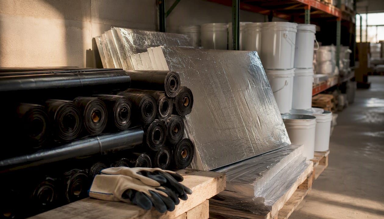
Self-adhered sheet membranes (foil-laminate or HDPE)
These are the workhorses of commercial vapor barrier applications. Foil-faced membranes typically achieve 0.02–0.05 perms; HDPE-based sheets fall in a similar range. Self-adhered products bond directly to the substrate, eliminating the need for separate adhesive and reducing the risk of voids. Common applications include under-slab vapor control, interior wall vapor barriers in cold-climate commercial construction, and roof vapor barriers below insulation in cold-roof assemblies.
Fluid-applied membranes and coatings
Applied by spray, roller, or trowel, fluid-applied products conform to irregular substrates and self-seal around penetrations better than sheet goods. Perm ratings vary widely by product and thickness, from below 0.1 perm for some hot-applied rubberized asphalts to 0.5–2.0 perms for thinner elastomeric coatings. Confirm the perm rating at the specified dry-film thickness, and verify that the product meets Class I thresholds if a vapor barrier (not just a retarder) is required.
Metal foils and aluminum facings
Aluminum foil achieves permeance near zero and is used as a facing on rigid insulation boards, duct wrap, and some roofing membranes. It is highly durable against diffusion but vulnerable to physical damage and corrosion at cut edges. In commercial roofing, foil-faced polyisocyanurate (polyiso) boards serve simultaneously as insulation and vapor retarder.
Rigid closed-cell foam sheathing
Closed-cell spray polyurethane foam (SPF) and extruded polystyrene (XPS) boards achieve Class I or Class II permeance depending on thickness. Two inches of XPS typically falls around 0.6–1.0 perm; closed-cell SPF at two inches is typically below 1.0 perm and can approach Class I at greater thicknesses. These materials are particularly useful in commercial wall assemblies where continuous exterior insulation also provides vapor control, eliminating the need for a separate interior membrane.
Coated gypsum and foil-backed board
Foil-backed gypsum board is a common interior vapor barrier in cold-climate commercial construction, particularly in metal-stud walls. The foil facing achieves Class I permeance while the gypsum provides fire resistance and substrate for finishes. Joints and penetrations must be carefully sealed; an unsealed electrical box or pipe penetration through foil-backed board effectively eliminates the vapor control at that location.
Vapor-barrier paints and coatings
Certain low-perm latex or alkyd paints are marketed as vapor retarders, typically achieving Class II permeance (0.5–1.0 perm) at standard application rates. True Class I performance from paint alone is rare and difficult to verify in the field. These products are more appropriate as supplemental vapor control or in mild climates where Class II is sufficient.
Pro Tip: In trafficable roof areas or high-traffic commercial walls, prioritize puncture resistance and adhesion durability over achieving the lowest possible perm rating. A membrane rated at 0.08 perm that survives foot traffic and mechanical abuse outperforms a 0.02-perm foil that tears during installation.
Where to place vapor barriers in commercial walls, roofs, and slabs
Placement is where specification errors most often occur. The right location depends on climate, assembly type, and whether the assembly has a reliable drying path.
Walls
In climate zones 5–8, place the vapor barrier on the interior (warm-in-winter) side of the insulation, between the insulation and the interior finish. This keeps the barrier warm enough to stay above the dew point and prevents vapor from reaching the cold sheathing layer. For commercial masonry facades, the hygric buffering capacity of the masonry changes the calculation: masonry can absorb and release significant moisture, so a vapor barrier behind a masonry veneer in a mixed climate may trap moisture rather than protect against it.
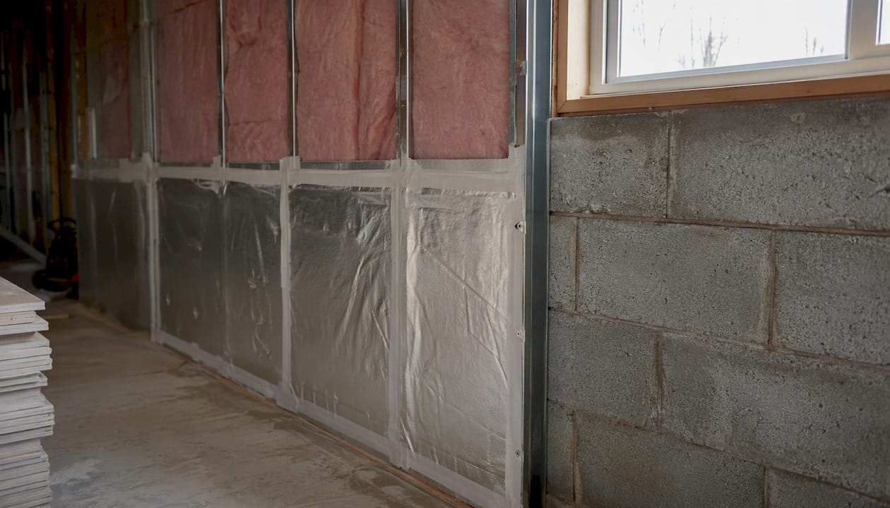
In climate zones 1–3, avoid interior vapor barriers. The vapor drive is often inward during the cooling season, and an interior barrier blocks drying to the inside. Exterior vapor-permeable air barriers or vapor-permeable assemblies are typically more appropriate. When planning a commercial siding replacement, this is the moment to reassess whether the existing vapor control layer is correctly placed for the climate.
In climate zones 4 and mixed climates, neither a blanket interior nor exterior vapor barrier is reliably correct. Hygrothermal modeling using tools like WUFI or THERM is the defensible approach.
Roofs
Commercial roof vapor barriers are most commonly specified in cold climates below the insulation layer (between the structural deck and the insulation) to prevent interior moisture from migrating into the insulation. In protected membrane or inverted roof assemblies, the waterproofing membrane sits above the insulation, and a separate vapor barrier below the insulation controls diffusion from the conditioned interior. Understanding the types of commercial roofing systems in play on a project is essential before specifying vapor control, because assembly sequence determines where the vapor barrier belongs.
Air sealing at the roof-wall transition, penetrations, and curbs is almost always more critical than the vapor barrier itself. A perfectly specified vapor barrier with unsealed penetrations provides little real protection.
Slabs
Under-slab vapor control membranes protect moisture-sensitive flooring finishes (hardwood, vinyl composition tile, epoxy coatings) and prevent ground moisture from elevating interior relative humidity. ASTM E1745 governs under-slab vapor retarder performance; Class A membranes (the most durable) are appropriate for most commercial applications. Joints should be lapped a minimum of 6 inches and taped; penetrations for conduit and pipes should be sealed with compatible mastic or tape.
Exceptions and special cases
- Below-grade assemblies: Hydrostatic pressure can overwhelm diffusion-only vapor barriers. Below-grade walls and slabs require waterproofing systems, not just vapor retarders.
- Process-moisture environments: Facilities like commercial kitchens, laundries, and natatoriums generate interior moisture loads that can exceed what a standard vapor barrier is designed to handle. Consult a building envelope engineer.
- Hot-humid conditioned spaces: In zones 1–2, a well-sealed building envelope with vapor-permeable assemblies often outperforms one with a vapor barrier that blocks inward drying.
Commercial vapor barrier installation: best practices for seams, terminations, and penetrations
A vapor barrier is only as effective as its weakest detail. The field of the membrane is rarely where failures originate; problems almost always start at seams, terminations, and penetrations.
Seam taping and sealing
- Use manufacturer-approved tape or sealant; not all pressure-sensitive tapes maintain adhesion over the service life of a commercial building.
- Lap seams a minimum of 6 inches for sheet membranes; some manufacturers require 12 inches at end laps.
- Roll seams firmly with a hand roller immediately after application to ensure full contact and eliminate air pockets.
- For fluid-applied membranes, apply a reinforcing fabric at seams and transitions before the topcoat.
Terminations and transitions
- Terminate sheet membranes into a reglet, under a counterflashing, or into a sealant pocket — never leave a free edge exposed to UV or mechanical damage.
- At window and door openings, coordinate vapor barrier termination with the window flashing sequence. The vapor barrier should integrate with the roof flashing system at the wall-to-roof transition to maintain continuity.
- At slab edges, carry the under-slab membrane up the foundation wall and tie it into the wall vapor control layer to prevent a gap at the most vulnerable thermal bridge location.
Penetrations
- Seal all mechanical, electrical, and plumbing penetrations with compatible mastic, foam, or pre-formed collars before the membrane is considered continuous.
- For fluid-applied systems, apply a bead of compatible sealant around each penetration and tool it into the wet membrane.
- Document penetration locations with photos before concealment; this simplifies future repairs and modifications.
Integration with the air barrier
The vapor barrier and air barrier are often separate products installed by different trades. Assign clear responsibility in the specification: who seals the transition between the vapor barrier and the air barrier at each condition (wall-to-roof, wall-to-slab, window rough opening). Overlaps between the two systems should be a minimum of 4 inches with compatible adhesive or tape.
Substrate preparation and weather windows
- Fluid-applied membranes require clean, dry substrates within the manufacturer’s temperature range, typically 40°F–100°F.
- Sheet membranes applied in cold weather may require substrate warming or a primer to achieve adequate adhesion.
- Allow fluid-applied membranes to cure fully before covering with insulation or cladding; covering a wet membrane traps solvent and can reduce adhesion.
Pro Tip: On commercial projects, require a mockup panel of at least 100 square feet that includes a seam, a penetration, and a termination condition before full installation begins. Test adhesion per the manufacturer’s pull-test method and document the result. This single step catches incompatibility issues and workmanship problems before they are buried under insulation.
Common mistakes and failure modes in commercial vapor barrier projects
Moisture failures in commercial buildings are rarely caused by a single catastrophic error. They accumulate from small specification oversights and workmanship lapses that compound over time.
Specification errors
- Double vapor control: Installing an impermeable membrane on both the interior and exterior of an assembly eliminates all drying capacity. Any moisture that enters through air leakage, condensation, or construction moisture has nowhere to go. This is among the most common errors in retrofit projects where a new exterior cladding system is applied over an existing interior vapor barrier.
- Wrong climate placement: Specifying an interior Class I vapor barrier in a hot-humid climate (zones 1–3) blocks inward drying during the cooling season and can cause chronic moisture accumulation behind the barrier.
- Ignoring air leakage: A perfectly installed vapor barrier with unsealed penetrations, gaps at transitions, or missing air barrier continuity will not prevent moisture problems. Air leakage bypasses the vapor barrier entirely.
Installation errors
- Poor seam and termination detailing, particularly at inside corners, window openings, and roof-wall transitions
- Inadequate surface preparation leading to adhesion failure of self-adhered or fluid-applied membranes
- Covering fluid-applied membranes before full cure
- Failing to seal penetrations added after the membrane is installed (a common problem during mechanical rough-in)
Failure symptoms and consequences
- Hidden condensation within insulation, detectable only by moisture scanning or invasive probing
- Mold growth on interior finishes, particularly at thermal bridges where surface temperatures drop below the dew point
- Corrosion of metal decking, fasteners, and structural members in roof assemblies
- Insulation saturation and loss of thermal performance, which can be significant in a high-R commercial roof assembly
- Flooring finish failure over slabs: adhesive bond failure, cupping of wood flooring, bubbling of vinyl, and efflorescence under epoxy coatings
Repairs are expensive because they typically require removing and replacing finishes, insulation, and sometimes structural components to access the failed membrane. Premature commercial roof failures frequently trace back to moisture-related insulation degradation that began with an incomplete or misplaced vapor control layer. The cost of getting the detail right during construction is a fraction of the cost of remediation.
Codes, standards, and how to write a vapor barrier specification
Three primary references govern commercial vapor barrier specification in the United States.
ASTM E96 defines the test methods for measuring water vapor transmission. As noted earlier, Method A (dry-cup) and Method B (wet-cup) produce different results for the same material. Your specification should state which method applies and what the maximum allowable perm is at that test condition. For a commercial vapor barrier, the threshold is ≤0.1 perm.
IECC 2021, Chapter 4 covers commercial energy efficiency requirements including envelope performance. The IECC references climate zones (defined by the Energy.gov climate zone map) to determine when vapor retarders are required and at what class. Climate zones 5–8 generally trigger requirements for Class I or II vapor retarders in specific assembly types. The IBC references the IECC for energy-related envelope requirements, so both documents apply to most commercial projects.
ASHRAE guidance, particularly ASHRAE 160 (Criteria for Moisture-Control Design Analysis in Buildings), provides the hygrothermal analysis framework for borderline or high-risk assemblies. When the IECC prescriptive path does not clearly apply, ASHRAE 160 analysis is the defensible alternative.
Sample specification language
A concise, enforceable vapor barrier specification for a commercial project should include:
- Material standard: “Vapor barrier shall be a Class I vapor retarder with a maximum permeance of 0.1 perm when tested in accordance with ASTM E96, Method B (wet-cup).”
- Substrate compatibility: “Installer shall verify substrate compatibility per manufacturer’s written instructions and submit product data and test reports prior to installation.”
- Seam and termination requirements: “Seams shall be lapped a minimum of 6 inches and sealed with manufacturer-approved tape. All penetrations shall be sealed with compatible mastic or pre-formed collars.”
- QA testing: “Contractor shall install a minimum 100-square-foot mockup panel including one seam, one penetration, and one termination condition. Adhesion shall be tested per manufacturer’s pull-test protocol and results submitted to the architect prior to proceeding.”
- Inspection: “Completed installation shall be inspected for continuity, adhesion, and proper termination prior to concealment. Deficiencies shall be repaired and re-inspected.”
Climate zone note: The IECC’s climate zone map places most of Connecticut in zone 5, which triggers requirements for Class I or II vapor retarders in commercial wall and roof assemblies. Verify the specific zone for your project address using the Energy.gov map before writing the specification.
Field inspection, testing, and QA for commercial vapor barriers
A vapor barrier that passes specification on paper but fails in the field provides no protection. A structured QA process catches problems before they are buried.
Pre-installation checks
- Verify substrate is clean, dry, and within the manufacturer’s temperature range.
- Confirm product data sheets match the specified perm class and test method.
- Check that all penetration locations are marked and that mechanical rough-in is complete before membrane installation begins.
- Review the mockup acceptance criteria with the installer before work starts.
Field QA during installation
- Conduct visual continuity checks at the end of each work shift, before any covering material is applied.
- Test seam adhesion by attempting to peel back a corner of tape at random locations; adhesion failure at this stage is far cheaper to fix than after insulation is installed.
- For under-slab membranes on sloped decks, a flood test (ponding water for 24 hours) can verify continuity before the slab pour.
- Use infrared thermography or capacitance moisture meters post-installation to identify wet spots or voids in the membrane that are not visible to the naked eye.
Laboratory verification
When product data is ambiguous or a substitution is proposed, request material samples and have them tested per ASTM E96 by an independent laboratory. This is particularly important for fluid-applied products where perm values are thickness-dependent and field application thickness can vary.
Post-occupancy monitoring
For high-risk assemblies (cold storage, natatoriums, process-moisture environments), install relative humidity sensors within the assembly at the vapor barrier plane and monitor readings through the first heating and cooling season. Sustained elevated readings indicate a continuity problem that should be investigated before it causes structural damage.
Pro Tip: When you are the property manager rather than the contractor, ask for three specific deliverables at project closeout: the mockup test results, a photographic log of penetration sealing, and the manufacturer’s warranty documentation. If the contractor cannot produce all three, the installation has not been properly documented and your warranty may be unenforceable.
A practical checklist for specifiers and property managers
Use this checklist during design meetings or pre-bid evaluations to confirm that vapor control has been fully addressed.
- Climate zone confirmed: Identify the project’s IECC climate zone using the Energy.gov map. Record whether the zone triggers a code-required vapor retarder class.
- Vapor drive direction established: Determine the dominant vapor drive direction (inward or outward) based on climate and occupancy. For mixed climates, flag for hygrothermal analysis.
- Occupancy moisture loads assessed: If the building use generates elevated interior humidity (kitchens, pools, labs, cold storage), note the required perm threshold and whether a Class I barrier is needed regardless of climate.
- Drying path confirmed: Identify at least one drying direction in the assembly. Confirm that no impermeable layer blocks drying on both sides of the cavity.
- Perm threshold specified: Write the maximum allowable perm and the ASTM E96 test method (A or B) into the specification.
- Air barrier continuity addressed: Confirm that the air barrier is continuous and that responsibility for each transition (wall-to-roof, wall-to-slab, penetrations) is assigned in the contract documents.
- Material compatibility verified: Check that the vapor barrier product is compatible with adjacent insulation, adhesives, and air barrier products.
- Durability and service life matched to use: For trafficable or high-abuse locations, specify minimum puncture resistance in addition to perm class.
- QA requirements written into the spec: Include mockup requirements, adhesion testing, and inspection hold points before concealment.
- Sequencing and warranty documented: Confirm that the installation sequence allows each trade to complete its tie-ins before the next layer is applied, and that warranty documentation will be provided at closeout.
Practical notes from an experienced exterior contractor
Vapor control details look straightforward on drawings. In the field, they are where schedules compress, trades overlap, and small gaps get covered before anyone notices.
Sequencing is the most common source of problems. On commercial envelope projects, the roofing trade and the cladding trade often work on overlapping schedules. The vapor barrier at the wall-to-roof transition needs to be completed and inspected before either trade covers it. Assign that transition explicitly in the subcontract scope — if it belongs to everyone, it belongs to no one.
Weather windows matter more than most specs acknowledge. Fluid-applied membranes applied below 40°F or over damp substrates will not achieve the adhesion values the product data sheet promises. Build weather contingency into the schedule, and require the installer to log ambient and substrate temperatures at the time of application. That log is your evidence if an adhesion failure is disputed later.
Mechanical penetrations are the most reliable source of continuity failures. Mechanical contractors typically rough in conduit, pipes, and ductwork after the membrane is installed. Every penetration that goes through the vapor barrier after the fact is a potential void. The solution is to complete mechanical rough-in before membrane installation wherever possible, and to require the membrane installer to be present when any post-installation penetration is made.
Document everything before it is covered. Photographs of completed seams, penetration seals, and terminations take minutes to capture and can save weeks of dispute resolution if a moisture problem surfaces years later. Make photographic documentation a contractual requirement, not a courtesy.
Pro Tip: At initial construction, detail every penetration location as if the building will be modified in 10 years, because it will be. Oversized sleeves with removable caps at known future penetration locations cost almost nothing during construction and save significant membrane repair costs when the building owner adds a new HVAC unit or data line later.
The case for getting vapor control right the first time
The conventional wisdom in commercial construction is that vapor barriers are a safety net — install one and moisture problems go away. That framing gets buildings into trouble.
A vapor barrier is a precision tool, not a default layer. Used correctly, in the right climate, in an assembly designed with a clear drying path, it protects insulation and structure from a specific and predictable moisture load. Used incorrectly — in the wrong climate, without air barrier continuity, or sandwiched between two impermeable layers — it creates a sealed environment where any moisture that enters has no exit. The repair costs in that second scenario routinely exceed the original construction cost of the entire envelope assembly.
The more useful default is this: start with a continuous, well-detailed air barrier and a reliable drainage plane. Then ask whether the specific assembly, in the specific climate, with the specific occupancy, actually needs diffusion control on top of that. For most commercial buildings in mixed climates, the answer is no — or at most, a Class II retarder. For cold-climate buildings with high interior humidity loads, the answer is yes, and the specification should be precise about perm class, test method, and QA requirements.
Building Science Corporation’s BSD-106 makes this point directly: vapor barriers are a cold-climate artifact that have been misapplied for decades. The cost of that misapplication shows up in moisture callbacks, mold remediation, and premature roof replacements that could have been avoided with a more deliberate specification process.
Jsignorexteriors supports commercial vapor-control projects in Connecticut
With more than 30 years of experience on commercial envelopes across Connecticut, Jsignorexteriors handles the full scope of vapor-control work that building owners and property managers need: envelope assessments, specification support, installation of roofing and wall assemblies with integrated vapor and air barrier detailing, and QA documentation at project closeout.

Connecticut’s climate zone 5 classification means most commercial buildings here have a genuine need for vapor control in roof and wall assemblies, and getting the sequencing and detailing right requires a contractor who understands how roofing, siding, and waterproofing systems interact. Jsignorexteriors coordinates those trades on a single contract, so transitions between systems are assigned, inspected, and documented rather than left to chance.
If you manage a commercial property in Connecticut and want a professional assessment of your building envelope’s vapor control, request a consultation with our commercial roofing team. We will review your assembly, identify any gaps in vapor or air barrier continuity, and provide a clear scope of work with no obligation.
Sources
These are the primary documents to consult when specifying, designing, or evaluating commercial vapor control.
- How to Identify and When to Select a Commercial Vapor Barrier | Henry Blog
- BSD-106: Understanding Vapor Barriers | Building Science Corporation
- Vapor Barriers | Building Science Education
- ASTM E96 – Standard Test Methods for Water Vapor Transmission of Materials
- IECC 2021 — Chapter 4: Commercial Energy Efficiency (ICC Codes)
- Energy